
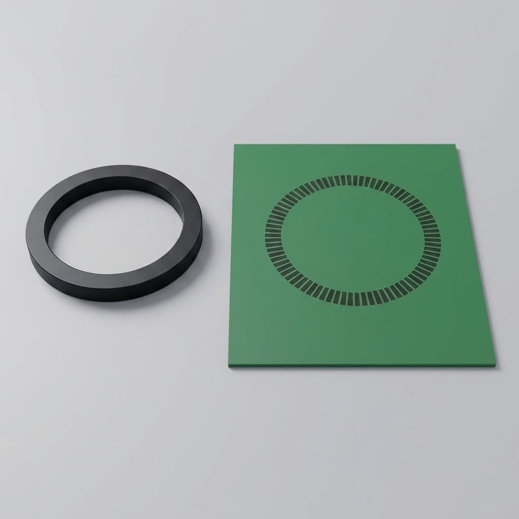
ASIL-D Sensor Magnet Requirements: Engineering & Procurement Guide
ASIL-D sensor magnet guide for ISO 26262 programs: compare materials, thermal drift, stray-field immunity, validation evidence, and RFQ controls.
Decision brief
Who this is for
Automotive Tier 1 procurement, application engineers, and functional safety managers.
What you can decide
- How to specify permanent magnets for ASIL-C/D compliant dual-die sensor assemblies.
- When to upgrade from NdFeB to SmCo or GBD NdFeB for high-temperature stability.
- How to define stray-field immunity requirements in RFQs.
Evidence included
- ASIL-D sensor magnet specification comparison table.
- Procurement checklist for safety-critical magnets.
Practical boundaries
- This guide focuses on the permanent magnet component of the sensor system, not the IC internal diagnostics.
The transition to Electric Vehicles (EVs) and advanced Advanced Driver Assistance Systems (ADAS) has pushed automotive functional safety into the spotlight. For procurement teams, hardware architects, and application engineers sourcing sensor magnets, the ISO 26262 ASIL-D (Automotive Safety Integrity Level D) standard changes everything about how components are specified, validated, and purchased.
Scope note: this guide is written for global automotive sourcing programs as of July 20, 2026. It focuses on the permanent magnet and magnetic target in the sensor assembly; the final ASIL claim still depends on the buyer's sensor IC diagnostics, mechanical design, software safety case, and OEM validation plan.
If you already have a sensor IC, air-gap target, and temperature profile, send the package through our contact/RFQ page for a magnet feasibility review before locking the drawing.
You can no longer buy a generic N52 disc magnet off the shelf and expect it to pass an ASIL-D system audit for an EV traction motor, steer-by-wire, or brake-by-wire system. The stakes are simply too high.
In safety-critical automotive applications, the sensor integrated circuit (often a dual-die Hall effect, GMR, or TMR sensor) relies completely on the target permanent magnet to be predictable, stable, and flawless across extreme temperatures, mechanical vibrations, and external electromagnetic interference. If the magnet degrades over time, demagnetizes due to heat, or cracks due to thermal shock, the redundant sensor ICs will trigger a safety fault. This fault can potentially disable the vehicle or force it into a restricted "limp home" mode.
This comprehensive guide covers the critical specifications, material choices, failure risks, and procurement checklists required when sourcing sensor magnets for ASIL-C and ASIL-D automotive applications.
Key Conclusions for Buyers and Engineers
- Redundancy Demands Tighter Tolerances: ASIL-D systems typically use dual-die sensors. The magnet must provide a perfectly uniform flux density across a larger sensing area to ensure both IC dies read identical mechanical positions. Any inconsistency will be flagged as a diagnostic error.
- Thermal Stability is Equivalent to Safety: Standard Neodymium (NdFeB) magnets lose significant field strength above 100°C. High-temperature environments like traction motors require Grain Boundary Diffusion (GBD) NdFeB or Samarium Cobalt (SmCo) to prevent high-temp demagnetization from triggering false sensor failures.
- Stray-Field Immunity Dictates Magnetization Precision: To combat electromagnetic noise from EV high-voltage cables, modern sensors use differential measurement techniques. This requires the target magnet to have precise multi-pole or diametrical magnetization to create a clean spatial gradient that the IC can interpret accurately amidst noise.
- Supplier Capabilities Must Mature: A supplier providing ASIL-D ready magnets must offer comprehensive PPAP (Production Part Approval Process), batch-level traceability, Cpk data on magnetic flux, and rigorous environmental testing (HAST, salt spray) that goes far beyond consumer electronics standards.
Why ASIL-D Changes Magnet Requirements
Functional safety under the ISO 26262 standard focuses heavily on preventing unreasonable risks due to hazards caused by malfunctioning behavior of electrical and electronic systems. For a magnetic position, angle, or speed sensor, a "malfunction" could be characterized by a complete loss of signal, a "frozen" signal that doesn't update, or an incorrect position reading that tells a control unit the steering wheel is straight when it is actually turned.
To mitigate these risks to an acceptable level, ASIL-D sensor ICs employ a multi-layered defense strategy:
- Dual-Die Redundancy: Two independent sensing elements are packaged within a single IC housing. If one fails, the other can still operate, or at least identify the discrepancy.
- Internal Diagnostics: Built-in test coils and circuitry continuously verify that the sensing elements are responding correctly to magnetic stimuli.
- Signal Cross-Checking: The system continuously compares the outputs of the two redundant dies. If they diverge beyond a tightly defined threshold, the system declares a fault.
The Crucial Role of the Magnet: In this architecture, the permanent magnet is the single point of truth. It is the physical reference for the entire electronic measurement. If the permanent magnet shifts physically due to adhesive failure, degrades thermally, or has a manufacturing defect (like an uneven coating causing localized rust and subsequent air-gap changes), the dual-die sensor might detect a discrepancy and throw a fault.
Therefore, the magnet's mechanical tolerances, magnetic alignment, and environmental resistance must be specified to an order of magnitude tighter than what is acceptable in consumer or industrial applications. The magnet must be treated not as a piece of hardware, but as an integral part of the safety loop.
High-Temperature Stability: GBD NdFeB vs. SmCo
In many automotive applications, particularly within the powertrain or braking systems, ambient temperatures are punishing. An EV traction motor resolver, an Electric Power Steering (EPS) motor position sensor, or a brake-by-wire actuator will routinely experience temperatures hitting 150°C, with localized hot spots potentially climbing even higher during peak load conditions. For adjacent material and coating options, compare our high-temperature sensor magnets capability page against the RFQ limits below.
When a permanent magnet gets hot, its magnetic field strength drops. This is a physical property known as the Reversible Temperature Coefficient (RTC). When the magnet cools down, the field returns to normal. However, if the magnet gets too hot—exceeding its maximum operating temperature or dropping below the knee of its demagnetization curve—it suffers irreversible demagnetization. If the field drops permanently below the sensor IC's minimum sensitivity threshold, the ASIL-D diagnostic algorithms will instantly flag a critical failure.
Here is a detailed comparison of magnetic materials and their suitability for high-temperature, high-safety automotive environments:
| Material Type | Max Operating Temp | Reversible Temp Coeff (Br) | ASIL-D Fit | Cost Impact | Key Characteristics & Risks |
|---|---|---|---|---|---|
| Standard NdFeB (N/M/H grades) | 80°C - 120°C | -0.11 %/°C | Low (Avoid for safety) | Baseline | Prone to severe degradation at EV under-hood temperatures. High risk of irreversible loss. |
| High-Temp NdFeB (SH/UH grades) | 150°C - 200°C | -0.10 %/°C | Medium (Needs compensation) | +15% to 30% | Requires heavy Dysprosium (Dy) doping. Better temp resistance, but field still drops notably at 150°C. |
| GBD NdFeB (Dy/Tb Diffused) | 180°C - 220°C | -0.09 %/°C | High (Excellent balance) | +40% to 60% | Grain Boundary Diffusion limits heavy rare-earth usage to the outer layers, maintaining high Br while boosting Hcj. |
| SmCo (Samarium Cobalt 2:17) | 250°C - 350°C | -0.03 %/°C | Very High (Ultimate stability) | +100% or more | Exceptionally stable over temperature, no coating needed for rust prevention. Very brittle and expensive. |
| Compression Bonded NdFeB | 150°C | -0.11 %/°C | Medium (Good for complex) | Comparable | Lower flux density, but allows complex multipole rings with tight mechanical tolerances without machining. |
| Sintered Ferrite | 250°C | -0.20 %/°C | Low (Weak field) | -70% | Great temp and corrosion resistance, but often too weak to provide the necessary signal-to-noise ratio (SNR) for stray-field immune sensors. |
| Injection Bonded Ferrite | 120°C | -0.20 %/°C | Low (Weakest field) | -80% | Only suitable for low-temp, low-accuracy applications (e.g., simple wake-up switches), not precision ASIL-D tracking. |
Procurement Advice: Never rely solely on the generic "Max Operating Temperature" spec found on a supplier's datasheet. This is a theoretical number. Always ask your supplier to provide the demagnetization curve (B-H curve) measured at your specific maximum operating temperature and at the exact permeance coefficient (Pc) of your specific magnet geometry. A thin disc magnet will demagnetize much faster than a thick cylinder at the same temperature.
Stray-Field Immunity and Magnet Geometry
Modern electric vehicles are incredibly noisy electromagnetic environments. High currents flowing through thick battery cables from the battery pack to the inverter and traction motors generate powerful stray magnetic fields. These external fields can easily overpower the intended, relatively weak signal originating from a small sensor magnet located nearby.
To achieve ASIL-C and ASIL-D compliance, Tier 1 suppliers and sensor IC manufacturers (like Infineon and Melexis) utilize stray-field robust topologies. These sensors, often based on differential Hall effect or Tunnel Magnetoresistance (TMR) technology, do not measure the absolute strength of the magnetic field. Instead, they measure the spatial gradient or the angle of the magnetic field vector. By measuring the difference between two points, any homogeneous external stray field is mathematically canceled out.
However, this sophisticated sensing technology shifts a massive burden onto the magnet manufacturer. The magnet must now produce an incredibly accurate and specific magnetic field shape.
- Diametrical Magnetization: For end-of-shaft rotary position sensors, the magnet is typically a disc magnetized across its diameter. The angle of this magnetization axis must be perfectly aligned with the mechanical features of the magnet (like a D-cut or alignment notch). Often, this must be accurate to within ±1 degree or better. See diametric sensor magnets for the product-level constraints behind this geometry.
- Multi-pole Ring Magnets: For off-axis or linear measurements, multi-pole rings are used. The "pole pitch error" (the microscopic physical variance in distance between the transition from a North pole to a South pole) must be tightly controlled, frequently to ±0.5% or better. If the poles are uneven, the differential sensor will miscalculate the position.
Visualizing Magnetic Field Gradients
In ASIL-D applications, both sensing dies must read within a strict tolerance band of the magnetic field curve. A geometrically imperfect magnet will warp this curve, causing a discrepancy between the dies.
Common Failure Modes and Risks
When validating a magnet for an ASIL-D application, engineering and procurement teams must analyze multiple failure modes beyond just magnetic strength:
- Coating Failure and Corrosion: Neodymium (NdFeB) is highly susceptible to oxidation (rust). If the protective coating (like Ni-Cu-Ni or Epoxy) contains pinholes or scratches, moisture will penetrate. The rust expands, physically pushing the magnet out of alignment, changing the air gap, or shedding conductive magnetic dust onto the sensor PCBA.
- Mechanical Fracture: Magnets are ceramics. SmCo, in particular, is incredibly brittle. High mechanical shocks, vibrations, or improper press-fit assembly processes can cause the magnet to chip or crack. A cracked magnet instantly alters the magnetic field topology, leading to sensor failure.
- Adhesive Degradation: Magnets are often glued to shafts. If the adhesive degrades over 15 years of thermal cycling (-40°C to +150°C), the magnet can slip rotationally. A slip of just a few degrees in a steering angle sensor is catastrophic.
- Aging and Micro-structural Changes: Over decades, the internal grain structure of the magnet can relax, leading to a slow, irreversible loss of magnetic flux. Accelerated aging tests are critical to predict end-of-life (EOL) performance.
Specific ASIL-D Applications and Magnet Requirements
Different subsystems within a modern vehicle have unique demands on the magnetic circuit. Understanding the specific application helps in tailoring the magnet specification, avoiding over-engineering while ensuring absolute safety.
1. Electric Power Steering (EPS) and Steer-by-Wire
In steer-by-wire systems, there is no mechanical linkage between the steering wheel and the road wheels. The steering angle sensor is the absolute source of truth.
- Requirement: Ultra-high precision angle measurement over 360 degrees.
- Magnet Choice: Typically a diametrically magnetized disc or a small ring magnet. The magnetization axis must be virtually perfect.
- Material: SmCo is highly favored here because EPS motors generate significant heat, and any variation in the magnetic field over temperature will translate directly into a steering angle error.
2. Brake-by-Wire and Electronic Stability Control (ESC)
Brake pedal position sensors determine how much braking force to apply. A failure here could lead to sudden unintended braking or a complete loss of braking power.
- Requirement: Linear position sensing, often requiring the sensor to track the movement of a rod over several centimeters.
- Magnet Choice: Multi-pole linear magnetic strips or axially magnetized cylinder magnets moving relative to a fixed sensor.
- Material: High-temperature NdFeB or GBD NdFeB. The environment is hot, but the absolute extreme temperatures of the traction motor are usually avoided.
3. EV Traction Motor Resolvers and Commutation
The inverter needs to know the exact rotor position of the electric motor to apply the correct phase currents.
- Requirement: Extremely high-speed tracking (up to 30,000 RPM in modern EVs) in an environment saturated with electromagnetic noise and extreme heat.
- Magnet Choice: High-pole-count ring magnets on the rotor shaft, read by differential Hall or TMR sensors.
- Material: GBD NdFeB is the dominant choice, offering the best balance of high flux density (required to overpower stray fields) and resistance to demagnetization at 150°C - 180°C.
4. Electronic Throttle Control (ETC)
While perhaps less demanding than steer-by-wire, ETC still requires ASIL-C or ASIL-D compliance to prevent runaway acceleration.
- Requirement: Rotary position sensing over a limited angle (typically 90 degrees).
- Magnet Choice: Simple diametrically magnetized discs or arc segments.
- Material: Standard or slightly elevated temperature NdFeB is often sufficient, provided the packaging protects it from the harshest under-hood environments.
Supplier Communication & Buyer Decision Points
Procurement professionals must elevate their conversations with magnet suppliers when sourcing for functional safety. It is no longer a transaction based purely on dimensions and price.
Key Buyer Decision Points:
- Supplier Automotive Maturity: Does the supplier have IATF 16949 certification? Do they understand PPAP documentation, Control Plans, and FMEA (Failure Mode and Effects Analysis)?
- Testing Capabilities In-House: Can the supplier perform HAST, thermal shock, salt spray, and 100% automated magnetic angle testing in-line? Relying on third-party labs delays production and indicates a lack of process control.
- Traceability Depth: For ASIL-D, you often need lot-level or even piece-level traceability. If a field failure occurs, can the supplier trace the magnet back to the exact powder mixing batch?
- Material Alternatives: A good supplier will challenge your print. If you specify SH-grade NdFeB for a 160°C environment, a proactive supplier should suggest GBD NdFeB or SmCo and present the cost-benefit analysis.
For buyer-side qualification language, our automotive sensor magnets page explains how we keep certification claims evidence-dependent while still supporting RFQ, sample, and repeat-order documentation.
ASIL-D Sensor Magnet RFQ Checklist
When sending a Request for Quotation (RFQ) to a magnet supplier for a functional safety application, ensure you explicitly include these parameters to filter out unqualified vendors:
- Minimum Flux Density at End of Life (EOL): Do not just specify Day 1 flux. Specify the minimum mT or Gauss required at the maximum mechanical air gap, at maximum operating temperature, after 15 years of simulated aging.
- Reversible Temperature Coefficient (RTC) Limits: Define the absolute maximum allowable drop in field strength per degree Celsius.
- Coating Reliability Validation: For ASIL-D, rust is an unacceptable failure mode. Require 1000+ hours of Salt Spray Test (SST) or highly accelerated stress test (HAST) compliance. Consider specifying dual-layer coatings (e.g., Parylene or Epoxy applied over standard Ni-Cu-Ni).
- Magnetization Angle Tolerance: For diametrical or multi-pole magnets, specify the maximum angular deviation (e.g., ±1.0° or ±0.5°). Ask how they will measure this in mass production.
- Traceability Requirements: Demand batch-level traceability as a minimum, with associated Cpk data on magnetic flux and physical dimensions for every shipment.
- AEC-Q200 Compliance Framework: While permanent magnets do not perfectly fit the AEC-Q200 standard (which is designed for passive electrical components), ask suppliers to align their internal testing and PPAP with AEC-Q200 stress test criteria (mechanical shock, vibration, temperature cycling).
- Cleanliness Specifications: Magnetic dust or debris on the parts can short circuit the sensor IC. Specify a maximum particle size and weight per batch (technical cleanliness).
Next Steps for Your Procurement Team
Sourcing magnets for ASIL-C/D systems requires a manufacturing partner who intimately understands automotive PPAP, rigorous Cpk controls, and the physics of magnetic thermal degradation. If your current supplier only provides basic Gauss readings at room temperature and lacks an automotive mindset, you are carrying a massive, undocumented supply chain risk.
Need a reliable partner for safety-critical magnetic assemblies? Contact our engineering team for an in-depth design review, material selection consultation, and PPAP-ready samples tailored for your ISO 26262 application.
Sources & References
- ISO 26262-5:2018 - Road vehicles — Functional safety — Part 5: Product development at the hardware level. Official standard outlining hardware architectural metrics and diagnostic coverage.
- Infineon Technologies - Automotive Magnetic Sensors for Functional Safety, application overview detailing TMR and Hall sensor redundancy.
- Melexis - Triaxis Magnetic Position Sensors, technical overview of stray-field immune technology and differential sensing requirements for EV powertrains.
Reviewed by

Categories
More Posts
Specifying Magnets for Stray-Field Immune Position Sensors (2-Pole vs 4-Pole)
An engineering guide to selecting magnets for ISO 11452-8 compliant stray-field immune position sensors. Learn why upgrading your sensor IC often requires switching from a 2-pole to a 4-pole magnet.
Sensor Magnet Coatings: Ni-Cu-Ni, Epoxy, and Parylene Compared for Harsh Environments
An engineering and procurement guide comparing the three most common coatings for NdFeB sensor magnets. Covers salt spray resistance, thickness tolerances, failure modes, and cost.

Section 301 Tariff on Sensor Magnets: Why Magnetic Assemblies Reduce Your Landed Cost
How 2026 US tariff changes affect sensor magnet sourcing, why magnetic assemblies face lower duty rates than bare magnets, and what procurement teams should evaluate before the next PO.