
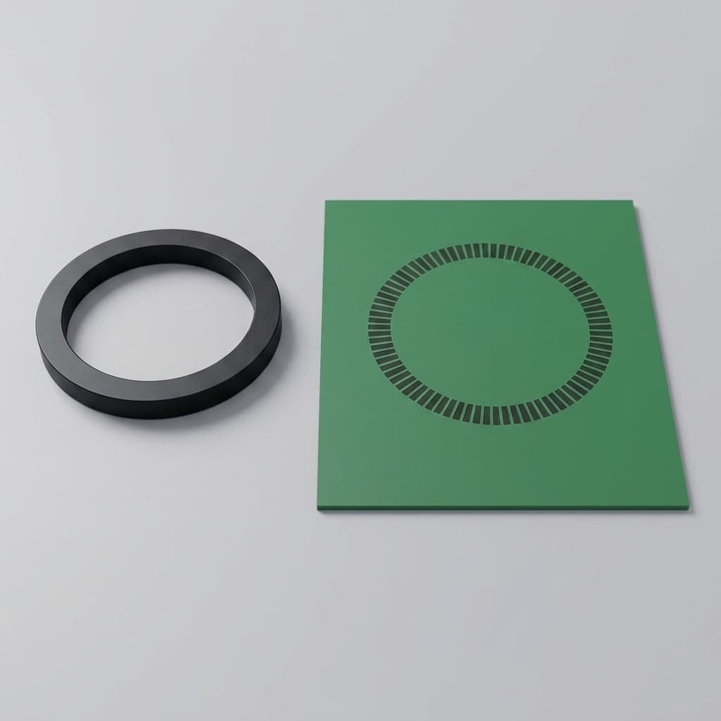
TMR vs Hall Effect Sensor Magnets: Target Specification Guide
Compare TMR vs Hall Effect sensor magnets for RFQ specs, field limits, materials, tolerances, and sourcing risk. Use the checklist to source target magnets.
Decision brief
Who this is for
Hardware architects, automotive Tier 1 procurement, and application engineers.
What you can decide
- How to adjust magnet specifications when migrating from Hall-effect to TMR sensor ICs.
- Whether to downgrade magnet material (e.g., Sintered NdFeB to Bonded Ferrite) for cost savings.
- How to define magnetic field strength constraints to prevent TMR saturation.
Evidence included
- Hall vs. TMR specification comparison table.
- Procurement RFQ checklist for TMR magnets.
Practical boundaries
- This guide focuses exclusively on the passive permanent target magnet requirements, not the internal electrical layout of the sensor ICs.
The landscape of magnetic position, speed, and angle sensing is shifting. For decades, the Hall-effect sensor has been the default choice for automotive and industrial magnetic sensing. As of July 23, 2026, Tunnel Magnetoresistance (TMR) technology is increasingly considered for applications requiring high precision, miniaturization, and ultra-low power consumption.
But what does this mean for the passive component that drives the entire system? The permanent target magnet.
For hardware architects, application engineers, and global procurement teams, the transition from Hall to TMR is not a simple "plug-and-play" swap of the IC. The fundamental physics of how TMR detects magnetic fields means that the specifications, material selection, and tolerances of your target magnet must change completely.
This comprehensive guide explores how magnet requirements evolve when migrating to TMR, the massive cost-saving opportunities available for procurement, and the critical engineering risks (like magnetic saturation) that must be mitigated in your next Request for Quote (RFQ).
Scope and limits: The target ranges below are starting points for passive permanent target magnets in rotary, linear, and speed-sensing assemblies. Always validate the final magnet against the selected IC datasheet, air gap, temperature range, mechanical stack-up, stray-field exposure, and end-of-line calibration method.
1. Executive Summary: The Shift to TMR
To understand why the magnet changes, we must briefly understand why the sensor changes.
Hall-effect sensors generate a voltage proportional to the magnetic flux density perpendicular to the sensor chip. They are robust, cheap, and reliable, but they suffer from relatively low sensitivity and high power consumption.
TMR sensors rely on quantum mechanical tunneling. Electrons tunnel through an ultra-thin insulating layer sandwiched between two ferromagnetic layers. The probability of tunneling (and thus the electrical resistance) changes dramatically based on the external magnetic field's orientation.
The result? TMR sensors can be far more sensitive than traditional Hall sensors, can consume very low current, and can provide strong signal-to-noise ratios when the magnet and mechanical stack-up are controlled.
For the target magnet, this changes the game in three ways:
- Less Field Required: You no longer need a massive, hyper-strong N52 Neodymium magnet to reach the sensor's threshold.
- Angle Over Amplitude: TMR is highly sensitive to the direction of the magnetic field (in-plane), rather than just the raw amplitude (vertical Z-axis).
- Danger of Saturation: An overly strong magnet will "blind" a TMR sensor, whereas a Hall sensor would simply output its maximum value.
2. The Mechanics: Why TMR Changes Magnet Requirements
When an engineer designs a magnetic system for a standard 3D Hall sensor, the primary goal is often to deliver "enough" magnetic flux across the air gap. If the air gap is large, the engineer specifies a thicker magnet, a higher grade of Sintered NdFeB (like N48SH), or a larger diameter.
With TMR, the paradigm flips. TMR sensors operate in a specific magnetic window defined by the IC supplier. Many TMR angle sensors specify a useful field around 20 mT to 80 mT at the IC surface, while some devices allow an extended range with reduced accuracy or a different calibrated operating band.
If you take a legacy Hall-effect target magnet that delivers 150 mT at the required air gap and pair it with a TMR sensor, you will saturate the sensing element.
The Saturation Problem
Magnetic saturation in TMR means the ferromagnetic free layer has aligned strongly enough with the external field that additional field strength produces little usable resistance change. If the magnet is too strong, or the air gap fluctuates and brings the magnet too close, the sensor can stop reading angular changes accurately and introduce severe harmonic distortion.
Therefore, the Maximum Operating Magnetic Field (B_max) becomes a critical hard-stop specification on the magnet drawing, just as important as the Minimum field (B_min).
3. Procurement Advantage: Downgrading Material and Shrinking Volume
For procurement professionals, the TMR revolution is excellent news. The permanent magnet is often one of the most expensive components in a sensor assembly, especially considering the volatile pricing of rare-earth elements like Neodymium, Praseodymium, and Dysprosium.
Because TMR requires significantly lower magnetic flux density, procurement can execute powerful cost-down strategies:
Strategy A: Extreme Miniaturization (Volume Reduction)
If the application still requires Sintered NdFeB (perhaps for high-temperature stability in an ASIL-D automotive environment), you can drastically reduce the physical size of the magnet. A 10mm x 3mm Hall target magnet might be replaced by a 4mm x 1.5mm TMR target magnet. This reduces the raw material weight by over 80%, directly driving down piece price and allowing for more compact end-product designs.
Strategy B: Material Downgrading
If space is not the primary constraint, you can maintain the legacy magnet size but downgrade the magnetic material.
- From Sintered NdFeB to Bonded NdFeB: Compression or injection-molded bonded magnets have roughly 30-50% of the magnetic strength of sintered magnets. They are cheaper, require no protective plating (saving coating costs), and can be molded into complex shapes with integrated mounting features (e.g., D-shaft holes), eliminating secondary machining.
- From Bonded NdFeB to Ferrite: For less demanding environments, procurement can migrate all the way down to injection-molded Ferrite. Ferrite is incredibly cheap, immune to corrosion, and uses no rare-earth elements. While its flux output is low, it is often perfectly sufficient for a highly sensitive TMR IC.
4. Visualizing the Magnetic Operational Window
To understand the difference, consider the "Goldilocks Zone" of magnetic field strength at the sensor IC surface.
As the chart shows, TMR demands a much tighter tolerance on the upper bound of the magnetic field. A magnet that works perfectly for a Hall sensor can push a TMR sensor outside its datasheet window unless the magnet, air gap, and calibration plan are changed together.
5. Side-by-Side Table: Hall vs. TMR Target Magnet Specs
To give engineers a clear baseline, here is a comparative breakdown of how magnet specifications typically shift when migrating technologies.
| Specification Parameter | Standard Hall-Effect Sensor Target | Advanced TMR Sensor Target | Impact on Magnet Manufacturing |
|---|---|---|---|
| Typical Required Field (Air Gap) | 30 mT to 100+ mT | 20 mT to 80 mT typical | TMR can allow weaker, cheaper materials when the IC datasheet supports the lower field. |
| Saturation Limit (Upper Bound) | Very High (often > 200 mT) | Datasheet-specific upper limit; extended ranges often trade off accuracy | TMR magnets require strict Br (Remanence) upper limits in QC. |
| Material Preference | Sintered NdFeB, SmCo | Bonded NdFeB, Injection Ferrite, SmCo | TMR shifts preference toward net-shape, low-flux materials. |
| Physical Size (Volume) | Medium to Large | Micro to Small | TMR drastically reduces raw material usage and BOM cost. |
| Magnetization Angle Tolerance | ±2.0° to ±3.0° | ±0.5° to ±1.0° | TMR relies heavily on precise angle; magnetizer fixtures must be CNC-machined to extreme precision. |
| Temperature Coefficient Sensitivity | High (Hall ICs struggle to compensate) | Moderate (TMR has better inherent stability) | May allow slight relaxation of high-temp magnet grades. |
| Stray Field Dependency | Requires strong magnet to overpower noise | Requires differential magnetics (multi-pole) | TMR may require complex multi-pole magnetization rather than diametrical. |
6. Magnetization and Geometric Tolerances
While TMR allows you to save money on raw materials, it does introduce a new cost driver: Precision.
Because TMR sensors are fundamentally measuring the angle of the magnetic field vector in the X-Y plane (rather than just the vertical Z-axis flux), the physical magnetization of the magnet must be incredibly accurate.
If you are specifying a diametrically magnetized disc for an end-of-shaft TMR steering angle sensor, the magnetic axis must perfectly bisect the physical cylinder.
The Error Stack-up:
- Geometric runout: Is the magnet perfectly round?
- Assembly eccentricity: Is the magnet glued perfectly in the center of the rotating shaft?
- Magnetization angle error: Did the magnet manufacturer magnetize the disc at exactly 0.00° relative to its physical geometry, or is there a ±2° skew?
For Hall sensors, a ±2° magnetization error might result in a manageable output error. For high-precision TMR sensors (which are often chosen precisely to achieve < 0.1° total system error), a ±2° magnet skew will completely destroy the system's accuracy budget.
Procurement Takeaway: You will save money on the material (buying Bonded NdFeB instead of Sintered N52), but you must invest a portion of those savings back into the supplier's quality control and magnetizing fixtures. Demand 100% automated inspection of the magnetization angle, not just flux density sampling.
7. Step-by-Step RFQ Checklist for TMR Magnets
If you are sending an RFQ to a magnet supplier for a new TMR application, ensure the drawing and documentation include the following explicit controls:
- Define the Maximum Flux Density: Do not just specify minimum Gauss/mT at the air gap. Explicitly state the maximum allowable flux density to prevent TMR saturation.
- Tighten Angular Tolerances: Specify the Magnetization Angle Tolerance (e.g., "Magnetic axis must align with physical datum A within ±1.0°").
- Material Re-evaluation: Explicitly ask the supplier: "Based on the low field requirement of 30mT at 2mm, can you quote an injection-molded Ferrite or Bonded NdFeB alternative to the requested Sintered NdFeB?"
- Specify the IC Model: Tell the magnet supplier exactly which TMR sensor IC you are using (e.g., TDK TAD4140, Allegro CT310, Infineon TLE5501). Experienced magnet engineers know the field windows and saturation limits of specific chips.
- Stray Field Configuration: If the TMR sensor uses differential sensing for stray-field immunity, ensure the magnet is specified as a multi-pole or specifically shaped target (like a bow-tie or dual-pole ring) as required by the IC.
- Temperature Demagnetization Limit: While TMR operates at lower fields, irreversible demagnetization at high temperatures (e.g., 150°C in an engine bay) will still shift the sensor out of calibration. Ensure the high-temperature Hc (Coercivity) is locked in.
8. Real-World Application Shifts
Where does this transition matter most as of 2026?
Electric Power Steering (EPS) & Steer-by-Wire: EPS requires extreme functional safety (ASIL-D) and absolute angular precision. By moving to TMR, Tier 1 automotive suppliers are achieving < 0.1° angular error. They are transitioning from large sintered SmCo magnets to tightly toleranced, smaller SmCo or high-temp bonded magnets.
E-Bike and Micro-mobility Powertrains: High-torque e-bike motors use magnetic position sensors for commutation. The shift to TMR allows these motors to use ultra-cheap injection-molded ferrite rings with multiple poles, saving dollars per unit while extending battery life due to the TMR sensor's micro-amp power draw.
Robotics and Joint Encoders: Collaborative robots (cobots) require absolute position sensing at every joint. The hollow-shaft designs benefit from TMR's ability to read off-axis magnetic fields from thin, multi-pole magnetic rings, eliminating the need for bulky optical encoders.
9. Frequently Asked Questions (FAQ)
Can I use my existing Hall-effect target magnet for a new TMR sensor?
Often, no. TMR sensors are vastly more sensitive than Hall sensors. A magnet designed for a Hall sensor might generate a magnetic field that is too strong for the TMR IC, leading to magnetic saturation and severe harmonic distortion. You typically need to shrink the magnet, increase the air gap, or change to a weaker magnetic material.
Why is TMR allowing procurement teams to save money on magnets?
Because many TMR angle sensors operate in a lower magnetic field window than legacy Hall magnet designs, procurement can often replace expensive sintered Neodymium (NdFeB) magnets with cheaper bonded NdFeB or even low-cost injection-molded Ferrite magnets. This can cut BOM cost while improving supply chain resilience against rare-earth pricing volatility, provided temperature stability and demagnetization margin still pass validation.
Is stray field immunity better with TMR or Hall magnets?
The IC technology dictates stray field immunity, usually via differential sensing. Because TMR works with weaker target fields, the signal itself is smaller relative to external noise (like a high-current EV busbar). However, modern differential TMR ICs excel at mathematically canceling this noise. The burden falls on the magnet: it must be highly precise in its angular magnetization to support this differential reading without introducing mechanical errors.
What is magnetic saturation in a TMR context?
Magnetic saturation occurs when the external magnetic field exceeds the TMR sensor's dynamic range. Unlike Hall sensors, which can tolerate very high fields with a mostly linear response, the tunneling magnetoresistance effect plateaus. If the target magnet is too strong, the sensor cannot accurately detect rotational or linear changes, freezing the output or creating non-linear jumps.
Do TMR magnets require tighter mechanical tolerances?
Yes and no. Because you can use a larger air gap, mechanical Z-axis tolerances (distance from sensor) can sometimes be slightly relaxed. However, because TMR relies heavily on the in-plane field direction (angle) rather than pure field amplitude, the angular magnetization tolerance during manufacturing must be extremely tight (often < ±1.0°).
10. Sources and References
This guide synthesizes engineering data from leading magnetics and semiconductor manufacturers. For deeper IC-level technical specifications, consult the following foundational resources:
- NVE - AAT003 TMR Angle Sensor Datasheet - TMR angle-sensor operating behavior and magnetic field guidance from a sensor manufacturer.
- Allegro MicroSystems - AN119 TMR for 2D Angle Sensing - TMR sensing principle, angle error sources, and 2D angle-sensing behavior.
- Allegro MicroSystems - AN120 CT310 Application Guide - Practical TMR application guidance, including linear and saturation behavior for a 2D TMR angle sensor.
11. Conclusion: Specifying for the Future
The transition from Hall-effect to TMR sensing is an opportunity for engineering to achieve unprecedented precision and for procurement to strip unnecessary costs out of the bill of materials. However, treating the permanent target magnet as an afterthought is the fastest way to fail a TMR design.
By understanding magnetic saturation, demanding strict angular tolerances, and aggressively exploring alternative materials like bonded NdFeB and Ferrite, you can optimize your sensor assemblies for the next generation of smart hardware.
Are you transitioning a sensor design from Hall to TMR? Don't guess on the magnetic specifications. Contact our engineering team today for a free design review. We can run magnetic FEA simulations to ensure your new TMR sensor is paired with the perfect, cost-optimized target magnet.
Reviewed by

Categories
More Posts
Tolerance Stack-Up in Sensor Magnet Assemblies: How to Protect Your Sensing Margin
A practical guide to mechanical and magnetic tolerance stack-up in sensor magnet assemblies, covering air gap variation, field strength margin, and how to prevent false triggers or missed events in production.
ASIL-D Sensor Magnet Requirements: Engineering & Procurement Guide
ASIL-D sensor magnet guide for ISO 26262 programs: compare materials, thermal drift, stray-field immunity, validation evidence, and RFQ controls.

Bonded vs. Sintered NdFeB for Multipole Magnetic Encoders
A comprehensive procurement and engineering guide comparing bonded and sintered NdFeB magnets for rotary encoders, covering magnetic strength, tooling costs, and assembly yield.