
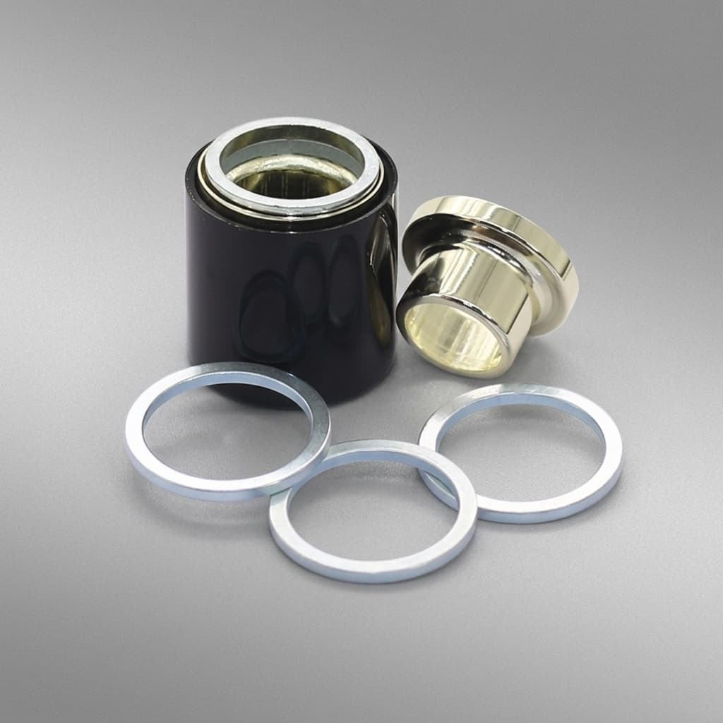
Specifying Magnets for Stray-Field Immune Position Sensors (2-Pole vs 4-Pole)
An engineering guide to selecting magnets for ISO 11452-8 compliant stray-field immune position sensors. Learn why upgrading your sensor IC often requires switching from a 2-pole to a 4-pole magnet.
Decision brief
Who this is for
Hardware designers, electrical engineers, and procurement teams specifying magnetic position sensors for EVs, industrial robotics, and high-power applications.
What you can decide
- Whether to use a 2-pole diametric or 4-pole multipole magnet for a new SFI sensor IC.
- How to adjust mechanical air gap tolerances due to the steeper magnetic field drop-off of 4-pole magnets.
- Selecting the right high-temperature material (SmCo vs NdFeB) for stray field immune systems in electric vehicle traction motors.
Evidence included
- Comparison table of 2-pole vs 4-pole field characteristics and air gap sensitivity.
- Analysis of gradient sensing principles required by ISO 11452-8.
- Material selection matrix for high-stray-field environments (e.g., EVs).
Practical boundaries
- Requirements vary heavily by IC manufacturer (e.g., Melexis Triaxis® vs Allegro vs Infineon). Always validate the pole count requirement in the IC datasheet before ordering magnets.
- Some specific "legacy compatible" SFI sensors can still use 2-pole magnets, but with reduced absolute field strength margins.
Last reviewed: July 21, 2026. This guide is for global engineering and procurement teams specifying sensor magnets for rotary or linear position sensors in EV, industrial robotics, and high-current electromechanical assemblies. It applies when the sensor IC advertises stray-field immunity or ISO 11452-8 style magnetic-field immunity; it does not replace the IC datasheet, finite-element magnetic simulation, or final EMC validation.
The transition to electrification in automotive and industrial sectors has introduced a massive new problem for position sensing: stray magnetic fields. High-current cables, busbars, and electric traction motors generate significant magnetic interference that can easily overpower the intended signal of a traditional magnetic position sensor.
To solve this, IC manufacturers (such as Melexis, Allegro, and Infineon) have introduced "Stray-Field Immune" (SFI) position sensors, often citing compliance with the ISO 11452-8 standard. These sensors use clever differential math to reject uniform external magnetic noise.
However, there is a catch that catches many hardware engineers and procurement teams off guard: upgrading the sensor IC often requires changing the magnet entirely. The legacy 2-pole diametric magnet you have been buying for years may no longer work.
This guide explores the engineering mechanics behind stray-field immunity, why gradient sensing changes your magnet requirements, and how to specify the correct 4-pole (or specialized 2-pole) magnet for your next-generation position sensor.
The Stray Field Problem and ISO 11452-8
In a traditional absolute position sensor system, a Hall effect or magnetoresistive (AMR/GMR/TMR) IC measures the absolute flux density of a rotating magnet. If a 2-pole diametric magnet applies a 30 mT field to the sensor, the IC calculates the angle based on the X and Y components of that 30 mT vector.
But what happens when a 500-amp power cable is routed 5 centimeters away from the sensor? That cable generates its own magnetic field—a "stray field." If the cable generates a 5 mT field, it vector-adds to the magnet's 30 mT field, skewing the angle calculation entirely. In safety-critical applications like electronic power steering (EPS), brake pedal position, or EV traction motor resolvers, this angular error is unacceptable and can lead to critical system failures.
ISO 11452-8 is the automotive standard governing a component's immunity to these magnetic fields. Modern SFI sensors are designed to maintain their accuracy even when subjected to stray fields up to 5 mT (roughly 4,000 A/m).
How Stray-Field Immunity Works: Gradiometric Sensing
To reject external magnetic noise, sensor designers moved from absolute field measurement to differential (gradiometric) measurement.
Instead of a single Hall plate measuring the total field, a gradiometric sensor uses multiple sensing elements separated by a known physical distance on the silicon die (e.g., one on the left, one on the right).
- The External Noise: A stray field from a distant power cable is effectively uniform across the tiny area of the sensor die. Both the left and right sensing elements see the exact same +5 mT interference.
- The Differential Math: The sensor IC subtracts the reading of the left element from the right element. Since both saw the +5 mT stray field, the interference is mathematically canceled out to zero (
5 - 5 = 0). - The Magnet's Role: For the sensor to measure anything at all, the target magnet must produce a field that is different at the left element versus the right element. It must produce a strong spatial magnetic gradient.
Why Legacy 2-Pole Magnets Fail with SFI Sensors
A standard 2-pole diametric magnet produces a highly uniform magnetic field across the center of its face. When placed over a small sensor IC, the left and right sensing elements see almost the exact same magnetic vector from the magnet.
If the sensor subtracts the left reading from the right reading to cancel noise, it will also accidentally cancel out the signal from the 2-pole magnet. The resulting signal-to-noise ratio drops drastically, and the sensor will likely throw a diagnostic error for "loss of magnetic field."
To provide the spatial gradient required by the IC's differential math, the magnet must present drastically different field vectors to the sensing elements simultaneously. This is why 4-pole magnets (or higher-order multipole magnets) are usually required.
Figure 1: Gradiometric sensors require opposing field vectors across their sensing elements to avoid canceling out the valid signal along with the uniform stray field noise.
The Hidden Trade-off: Air Gap Tolerance
When a purchasing department is told to simply "buy the 4-pole version of the same magnet," they often assume it will be a drop-in mechanical replacement. It is not.
Physics dictates that as the number of magnetic poles increases, the magnetic field strength drops off much more rapidly over distance (air gap). The magnetic flux "short circuits" to the adjacent opposing pole rather than projecting outward into space.
A 6 mm x 3 mm 2-pole magnet might provide a healthy 30 mT at a 4 mm air gap. If you change that exact same magnet to a 4-pole magnetization pattern, the field at 4 mm will be drastically weaker—perhaps only 5 mT.
This introduces serious mechanical engineering constraints:
- Tighter Air Gaps: The sensor IC must be placed much closer to the 4-pole magnet.
- Stricter Z-Axis Tolerances: Because the 4-pole field decays exponentially faster, a ±0.5 mm tolerance in your assembly stack-up will cause a much larger percentage change in field strength than it would with a 2-pole magnet.
Comparison Matrix: 2-Pole vs 4-Pole for Position Sensing
| Feature/Constraint | Traditional 2-Pole Diametric | Multipole (4-Pole) Gradient |
|---|---|---|
| Primary Sensing Method | Absolute Field (Amplitude/Vector) | Differential/Gradiometric |
| Stray Field Immunity (ISO 11452-8) | Low / Non-compliant | High (Up to 5 mT / 4 kA/m) |
| Field Drop-off over Distance | Gradual (Allows larger air gaps) | Very Steep (Requires tight air gaps) |
| Z-Axis Mechanical Tolerance | Forgiving (±0.5mm often acceptable) | Very Strict (Requires tight assembly) |
| XY Misalignment Sensitivity | Low to Moderate | High (Eccentricity causes angular errors) |
| Cost Implications | Standard pricing, widely available | Higher tooling cost for custom magnetizing fixtures |
Material Selection in High-Stray-Field Environments
Stray-field immune sensors are almost exclusively deployed in high-power, high-temperature environments like EV traction motors, electronic braking systems, and heavy robotics. Consequently, the magnet material must survive both the thermal load and the demagnetizing forces of adjacent fields.
- SmCo (Samarium Cobalt): The premier choice for EV resolver replacements and traction motor sensors. SmCo maintains its coercivity up to 300°C and is virtually immune to demagnetization from high-current spikes. It requires no anti-corrosion coating, saving processing time.
- High-Temperature NdFeB (UH / EH / AH Grades): Suitable for applications up to 180–200°C. While NdFeB offers a higher remanence (
Br), its intrinsic coercivity drops significantly at elevated temperatures. If a massive short-circuit current creates an immense stray field while the motor is hot, a NdFeB magnet may suffer irreversible partial demagnetization. - Ferrite: Generally avoided for SFI applications unless cost is the absolute driving factor and space is unlimited. Multipolling a ferrite magnet results in a very weak absolute field, meaning the air gap would need to be impractically small.
Engineering Tip: When specifying a 4-pole magnet for a Melexis Triaxis® or Infineon TLE-series SFI sensor, ensure your print explicitly calls out the magnetic gradient requirement (e.g., Delta B / Delta x in mT/mm) at the nominal air gap, rather than just a surface Gauss reading.
Upgrade Checklist: Migrating to Stray-Field Immune Sensors
Before releasing an RFQ for a new magnet to pair with your upgraded SFI sensor IC, run through this verification checklist:
- Verify IC Requirements: Read the specific application note for your SFI sensor. Does it require a 4-pole magnet, or does it feature a specialized 2-pole SFI mode (like some specific Melexis variants)?
- Recalculate the Air Gap: Do not reuse the mechanical air gap from your legacy 2-pole design. Run a magnetic simulation (or ask us to run one) to find the new Z-axis distance required to hit the IC's minimum gradient threshold (usually 1.5 to 3.0 mT/mm).
- Audit Assembly Tolerances: Check your tolerance stack-up. Because 4-pole fields drop off faster, ensure your worst-case maximum air gap still provides sufficient field strength.
- Check Eccentricity: Multipole setups are highly sensitive to XY off-axis misalignment (eccentricity). Ensure your shaft bearing runout is tight.
- Define Material Coercivity: If stray fields are a problem, temperature and demagnetization likely are too. Ensure your NdFeB grade (or SmCo selection) has sufficient intrinsic coercivity (
Hcj) at your maximum operating temperature.
Frequently Asked Questions
Why do stray-field immune sensors often require 4-pole magnets?
Many SFI sensors use gradiometric measurement—they measure the gradient (difference) of the magnetic field across multiple Hall plates rather than the absolute strength. A 4-pole magnet produces a steep, alternating spatial gradient that the IC can detect, while uniform external stray fields affect all Hall plates equally and are subtracted out mathematically.
Can I reuse my existing 2-pole diametric magnet when upgrading to a stray-field immune sensor?
Generally, no, unless the sensor IC explicitly states it supports a 2-pole SFI mode. If the IC requires a spatial gradient for differential math, a standard 2-pole magnet will not provide the necessary gradient across the die, and the sensor will either report an error or output corrupted angle data.
What is ISO 11452-8?
ISO 11452-8 is an automotive standard that defines test methods for a component's immunity to magnetic fields. Modern EV position sensors are often tested against this standard to prove they can operate accurately even in the presence of strong stray fields (up to 5 mT or 4 kA/m) from adjacent power cables or motors.
Does a 4-pole magnet have the same reading distance (air gap) as a 2-pole magnet?
No. As you increase the number of magnetic poles, the magnetic field lines become shorter, and the field strength drops off much more rapidly with distance. A 4-pole magnet will require a tighter, closer air gap than a 2-pole magnet of the exact same size and material to provide a reliable signal.
Need Help Specifying a Multipole Sensor Magnet?
Migrating to a stray-field immune architecture requires tight coordination between the sensor IC's mathematics and the physical magnetic field. You don't have to guess on the air gap or the material grade.
If you are upgrading an automotive or industrial position sensor to meet ISO 11452-8 requirements, our engineering team can help. Send us your target IC, your mechanical constraints, and your operating temperature. We will run the magnetic simulations, recommend the exact 4-pole configuration, and provide rapid prototyping.
Contact Engineering for a Magnet Consultation or explore our Multipole Ring Magnets capabilities.
References & Technical Sources
- ISO 11452-8:2015 Road vehicles — Component test methods for electrical disturbances from narrowband radiated electromagnetic energy — Part 8: Immunity to magnetic fields
- Melexis: Stray Field Immune Position Sensors (Triaxis® Technology)
- Analysis of Multipole Magnetic Encoders and Field Drop-off vs. Airgap (Sensors Journal, MDPI)
Reviewed by

Categories
More Posts
Magnetization Direction Selection for Sensor Magnets
How OEM buyers and engineers should choose axial, diametric, radial, and multipole magnetization for Hall, reed, encoder, speed, and position sensing applications.
ASIL-D Sensor Magnet Requirements: Engineering & Procurement Guide
ASIL-D sensor magnet guide for ISO 26262 programs: compare materials, thermal drift, stray-field immunity, validation evidence, and RFQ controls.
Sensor Magnet RFQ Checklist for OEM Buyers
A detailed RFQ checklist for custom sensor magnets, covering application data, magnetization, coating, tolerance, samples, inspection, packaging, and quote comparison.